Wasted Spark.
Coil primary
1= 0.7 Ohm
2=0.8 Ohms
3=0.6 Ohms
Coil secondary
1=12.2K ohms
2=12.3K ohms
3=12.3K ohms
Testing Ballast resistors
Part no: BR1
Resistance= 1.2 Ohms.
Standard Single tower coil
1. Wire up a ballast resistor in series with your coil primary winding values as shown in
the following diagram.
2. Connect an ammeter in series and note the current draw.
3. Measure and note the voltage drop across the ballast resistor.
4. Measure and note the voltage drop across the coil primary.
Current draw was 3.1A
Coil calculated voltage drop=6.51V
Coil measured voltage drop=10.6V
Ballast resistor calculated voltage drop=3.72
Ballast resistor measured voltage drop=1.3V
Sunday, November 14, 2010
WS7 Exhaust Gas Analysis
In the AIR
CO: 0%
HC: 0 ppm
CO2: 0.033%
O2: 21%
Start the engine measure when engine is cold.
CO: 0.07%
HC: 129 ppm
CO2: 15.11 %
O2: 0.33%
With the engine warming up
CO: 0.5%
HC: 100 ppm
CO2: 14.3%
O2: 0.48%
With engine at 2500 rpm
CO: 0.01%
HC: 17ppm
CO2: 15.18%
O2: 0.38%
Run the engine rich with propane and measure the results
CO: .011%
HC: 5 ppm
CO2: 15.16%
O2: 0.08
Make a vacuum leak and record the engine while running lean
CO: .004%
HC: 10ppm
CO2: 14.57
O2: 1.12%
The Lambda value was 1.053
Record the readings when accelerating.
CO: 0.039%
HC: 6ppm
CO2: 14.8%
O2: 0.52%
We were unable to complete experiment as power died.
Saturday, November 13, 2010
WS3B Dual Pattern
Using a dual trace (two channels A/B) oscilloscope capture the following
components and plot them against each other
The following sensors are used for WS3B:
MAP (analogue voltage) against Injectors (petrol)
RPM (Hall digital crank or distributor) against Injectors (petrol)
Oxygen sensor against Injectors (petrol)
Ignition primary against Injectors (petrol)
Ignition primary voltage against Ignition primary current
MAP (analogue voltage) against Injectors (petrol)
Signal Name: MAP Sensor vs Injectors
Volt/division: 10V
Time/division: 5ms

This waveform is comparing injector to the MAP sensor. This waveform was taken at idle so the MAP sensor voltage did not change. The injector waveform is normal. If more throttle is applied then there will be more voltage at the MAP sensor and the injectors will be opening and closing faster than at idle.If the MAP voltage did not change then the injection speed would not change so the engine wouldn't run at optimal performance.
RPM (Hall digital crank or distributor) against Injectors (petrol)

The injector is just the normal waveform with charging voltage, PWM time, Back EMF then back to charging voltage. The CKP sensor is fluctuating at idle producing AC voltage. As the CKP voltage increasing and the amplitude this means the engine is rotating faster. So the injectors will open and close quicker.
Oxygen sensor against Injectors (petrol)


We were unable to have the waveforms on the same screen because of the digital oscilloscope .The injector is just the normal waveform with charging voltage, PWM time, Back EMF then back to charging voltage. The oxygen sensor is fluctuating from rich to lean.
Ignition primary against Injectors (petrol)

We were unable to have the waveforms on the same screen because of the digital oscilloscope .The injector is just the normal waveform with charging voltage, PWM time, Back EMF then back to charging voltage. The beginning of the ignition waveform is charging voltage. The Voltage then drops to 0V by the ECU/ Igniter. Next a Back EMF is caused which is 40V. Which is when the spark is created. Next is spark duration and coil oscillations and back to charging voltage.
These two compare because when there is fuel being injected , you need a spark to complete combustion and create any form of power. As injectors spray quicker a spark needs to be created quicker. If there was no spark or injection the engine would not run. Unless it was just no spark or injection on 1 cylinder or 2 cylinders for some engines.
We were unable to get a waveform using current as it wasn't supported by the oscilloscope.

This waveform is comparing injector to the MAP sensor. This waveform was taken at idle so the MAP sensor voltage did not change. The injector waveform is normal. If more throttle is applied then there will be more voltage at the MAP sensor and the injectors will be opening and closing faster than at idle.If the MAP voltage did not change then the injection speed would not change so the engine wouldn't run at optimal performance.
RPM (Hall digital crank or distributor) against Injectors (petrol)
Signal Time: RPM Sensor vs Injectors
Volt/division: 10V
Time/division: 10ms

The injector is just the normal waveform with charging voltage, PWM time, Back EMF then back to charging voltage. The CKP sensor is fluctuating at idle producing AC voltage. As the CKP voltage increasing and the amplitude this means the engine is rotating faster. So the injectors will open and close quicker.
Oxygen sensor against Injectors (petrol)


We were unable to have the waveforms on the same screen because of the digital oscilloscope .The injector is just the normal waveform with charging voltage, PWM time, Back EMF then back to charging voltage. The oxygen sensor is fluctuating from rich to lean.
Ignition primary against Injectors (petrol)

We were unable to have the waveforms on the same screen because of the digital oscilloscope .The injector is just the normal waveform with charging voltage, PWM time, Back EMF then back to charging voltage. The beginning of the ignition waveform is charging voltage. The Voltage then drops to 0V by the ECU/ Igniter. Next a Back EMF is caused which is 40V. Which is when the spark is created. Next is spark duration and coil oscillations and back to charging voltage.
These two compare because when there is fuel being injected , you need a spark to complete combustion and create any form of power. As injectors spray quicker a spark needs to be created quicker. If there was no spark or injection the engine would not run. Unless it was just no spark or injection on 1 cylinder or 2 cylinders for some engines.
We were unable to get a waveform using current as it wasn't supported by the oscilloscope.
Friday, November 12, 2010
WS3 Ocilloscope Patterns
These sensors and actuators are used for the general lab worksheet WS3:
You need to capture at least 7 patterns from the lists below:
Sensors
MAP (digital)
MAF (digital)
TPS (switch type)
RPM (ac magnetic crank or distributor)
RPM (cam or distributor)
RPM (Hall digital crank or distributor)
Oxygen sensor
Actuators:
Injectors (petrol)
Injectors (diesel)
Idle air (digital 2 wire)
Idle air (digital 3 wire, both channels)
Ignition timing control (digital or analogue)
Ignition primary
Ground noise
Alternator ripple
Alternator Ripple


This above waveforms show the alternator ripple for idle and under load. With headlights , Air con, Radio ect on. The Alternator produces AC voltage and current . The battery requires DC voltage and current to charge properly. Diodes located within the alternator rectify the AC to DC. However, a small amount of AC can still be present and no harm is done. Problems can develop when alternator diode faults permit unacceptable amounts of AC to pass into the electrical systems.
Ignition Primary
MAF sensor

This waveform is showing MAF voltage when accelerator was pressed and released slowly to create this waveform. This shows as more air enters the engine there is a larger voltage produced.
MAP sensor
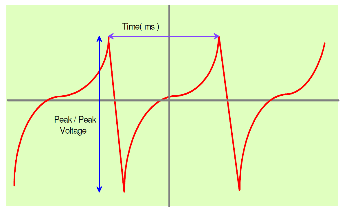
Secondary ignition pattern

This waveform is from the secondary ignition off a b16A integra.

You need to capture at least 7 patterns from the lists below:
Sensors
MAP (digital)
MAF (digital)
TPS (switch type)
RPM (ac magnetic crank or distributor)
RPM (cam or distributor)
RPM (Hall digital crank or distributor)
Oxygen sensor
Actuators:
Injectors (petrol)
Injectors (diesel)
Idle air (digital 2 wire)
Idle air (digital 3 wire, both channels)
Ignition timing control (digital or analogue)
Ignition primary
Ground noise
Alternator ripple
Alternator Ripple
Signal Name: Alternator Ripple
Volt/division: 188mV
Time/division: 2.1ms


This above waveforms show the alternator ripple for idle and under load. With headlights , Air con, Radio ect on. The Alternator produces AC voltage and current . The battery requires DC voltage and current to charge properly. Diodes located within the alternator rectify the AC to DC. However, a small amount of AC can still be present and no harm is done. Problems can develop when alternator diode faults permit unacceptable amounts of AC to pass into the electrical systems.
Ignition Primary
Signal Name: Ignition Primary.
Volt/division: 20V
Time/division: 2ms

The beginning of the waveform is charging voltage. The Voltage then drops to 0V by the ECU/ Igniter. Next a Back EMF is caused which is 40V. Which is when the spark is created. Next is spark duration and coil oscillations and back to charging voltage.
Ground Circuit.

This shows a low amount of voltage in the earth circuit which in term means low resistance. Our voltage from the waveform was 0.006V which is very small. This is acceptable from the manufacturers specifications. Anything above 0.050V is considered excessive.
The beginning of the waveform is charging voltage. The Voltage then drops to 0V by the ECU/ Igniter. Next a Back EMF is caused which is 40V. Which is when the spark is created. Next is spark duration and coil oscillations and back to charging voltage.
Ground Circuit.
Signal Name: Ground Circuit
Volt/division: 0.5V
Time/division: 2ms

MAF sensor
Signal Name: MAF sensor
Volt/division: 2V
Time/division: 50ms

This waveform is showing MAF voltage when accelerator was pressed and released slowly to create this waveform. This shows as more air enters the engine there is a larger voltage produced.
MAP sensor
Signal Name: MAP Sensor
Volt/division: 2V
Time/division: 100ms

The beginning of this waveform was the MAP at idling voltage. When accelerator was pressed and released this waveform was created. This shows voltage is increased as more throttle is applied. The Map sensor produces a voltage created from the vacuum inside the intake manifold.The data is used to calculate air density and determine the engine's air mass flow rate, which in turn determines the required fuel metering for optimum combustion. At the end of the waveform it is back to idling voltage.
Secondary ignition pattern
Signal Name: Secondary Ignition
Volts/division: 4KV
Time/division: 3.4ms

This waveform is from the secondary ignition off a b16A integra.

The ignition secondary picture shown above in the waveform is a typical picture from an engine fitted with electronic ignition. The waveform is an individual secondary High Tension (HT) picture that can be observed one cylinder at a time.
The secondary waveform shows the voltage required to jump the plug's electrode (A), and (B) the length of time that the HT is flowing across the spark plug's electrode after its initial voltage to jump the plug gap. This time is referred to as either the ‘burn time’ or the ‘spark duration’.
In the illustration shown, it can be seen that the horizontal voltage line in the centre of the oscilloscope (C) is at fairly constant voltage of approximately 3 kV. This voltage is referred to as the Sparkline kV. This voltage is the voltage required to maintain the spark flow across the plug's electrode, and is determined primarily by the secondary resistance within the HT circuit. From the 0 ms point on the scope to point D is the spark duration, in this case around 1.0 milliseconds. The waveform is then seen to drop sharply into what is referred to as the ‘coil oscillation’ (E). The coil oscillation should display a minimum number of peaks (both upper and lower) and at least of 4 - 5 peaks should be seen. A loss of peaks on this oscillation shows that the coil needs substituting. An example of a faulty coil and the subsequent loss of oscillations can be seen in Fig 1.2. The oscillation seen at point (F) is called the ‘polarity peak’; this voltage will be of the opposite polarity to the plug firing voltage as this is created when the magnetic flux is initially built, or at the start of the dwell period.
http://www.pc-oscilloscopes.com/primary-vs-secondary.html
Magnetic Distributor.
Signal Name: RPM (Magnetic, Distributor)
Volt/division: 10V
Time/division: 10ms

This is the voltage created at idle. As frequency increases so does voltage and amplitude. If the engine RPM was increased voltage and amplitude would also be increased. This is AC voltage.This works with a magnet and a pick up coil. As the air gap/ distance from the magnet gets further away voltage gets lower and when it gets closer voltage gets higher. The engine will die if the ECU does not receive this signal.

This is the voltage created at idle. As frequency increases so does voltage and amplitude. If the engine RPM was increased voltage and amplitude would also be increased. This is AC voltage.This works with a magnet and a pick up coil. As the air gap/ distance from the magnet gets further away voltage gets lower and when it gets closer voltage gets higher. The engine will die if the ECU does not receive this signal.
Thursday, November 11, 2010
WS3A Ocilloscope Patterns

MAP Sensor
This waveform was taken during a sharp acceleration. The voltage increases when more throttle is applied. Where the waveform starts is point A that is idling voltage. where it increases is when more throttle is applied and the end on the waveform is idling voltage again.
A fault to stop the MAP sensor working could be a broken connection, it could be open circuit inside the MAP sensor. Could have excessive resistance in the wiring loom. There could be a wiring fault when it was connected.
MAF sensor

The beginning for the waveform point (A) is the MAF at idle. at point B when it is increasing this is when the throttle was applied and more air was allowed into the engine.At point C it would be back to idle voltage.An electrical fault could be the wire not heating up and resistance doesnt change so voltage would always be the same.In this situation the voltage would always be 1.7V and would not change. The effect of this would be the car would run in limp home mode and idle will fluctuate. The graph would look like a straight line with no movement from idle voltage.
TPS .

We didnt have a linear type so we used a potentiometer type. point A is 0.5V whcih is idle voltage. It slowly increases as more throttle is applied this is because resistance decreases as more throttle is applied. This is a variable resistor. The problem could be excessive resistance in the earth wire. So there would be less voltage at the TPS. So the ECU would not know how much the throttle was applied. So the engine would run rich.
ECT
 This graph shows what happens to the ECT. It would be difficult to get a waveform showing the voltage changing. The ECT is a NTC thermistor. This means as temprature increasing resitance decreases. A problem again could be excessive resistance so the ECU would not recieve the correct voltage and would not know if the engine is hot or cold. If the ECT voltage didnt change stayed at 5V the engine would be constantly rich.
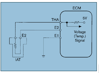
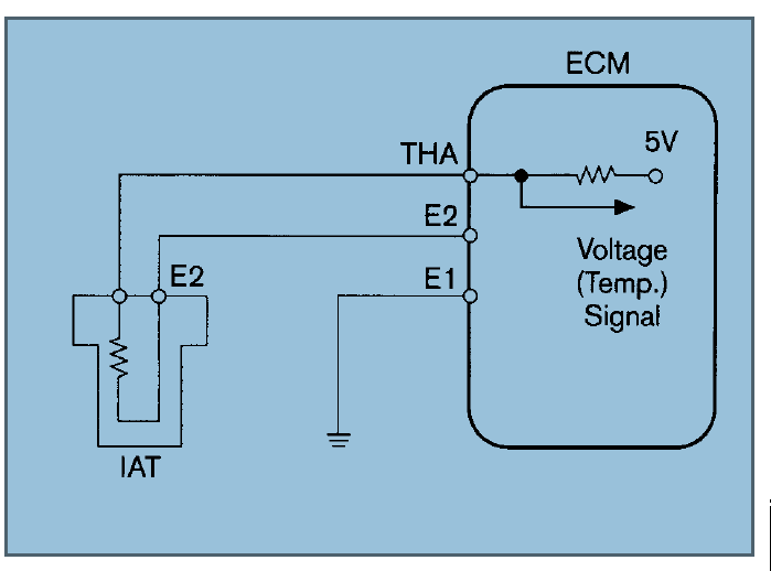
IAT

This graph shows that the IAT is NTC thermistor. resistance decreases with TEmprature. It would be difficult to get a waveform showing the voltage changing. Again the problem could be excessive ressistance within the circuit. This would mean the ECU would get incorrect signal voltage. This is how the ECU knows it is a cold start by comparing voltage to the ECT. if there was excessive ressitance the voltage would be lower.
MAF sensor

The beginning for the waveform point (A) is the MAF at idle. at point B when it is increasing this is when the throttle was applied and more air was allowed into the engine.At point C it would be back to idle voltage.An electrical fault could be the wire not heating up and resistance doesnt change so voltage would always be the same.In this situation the voltage would always be 1.7V and would not change. The effect of this would be the car would run in limp home mode and idle will fluctuate. The graph would look like a straight line with no movement from idle voltage.
TPS .

We didnt have a linear type so we used a potentiometer type. point A is 0.5V whcih is idle voltage. It slowly increases as more throttle is applied this is because resistance decreases as more throttle is applied. This is a variable resistor. The problem could be excessive resistance in the earth wire. So there would be less voltage at the TPS. So the ECU would not know how much the throttle was applied. So the engine would run rich.
ECT
 This graph shows what happens to the ECT. It would be difficult to get a waveform showing the voltage changing. The ECT is a NTC thermistor. This means as temprature increasing resitance decreases. A problem again could be excessive resistance so the ECU would not recieve the correct voltage and would not know if the engine is hot or cold. If the ECT voltage didnt change stayed at 5V the engine would be constantly rich.
IAT

This graph shows that the IAT is NTC thermistor. resistance decreases with TEmprature. It would be difficult to get a waveform showing the voltage changing. Again the problem could be excessive ressistance within the circuit. This would mean the ECU would get incorrect signal voltage. This is how the ECU knows it is a cold start by comparing voltage to the ECT. if there was excessive ressitance the voltage would be lower.
WS5 Scan Tool Diagnostics
Scan Tool readings.
Engine Load MAP 0.9 V
Engine RPM RPM 750 RPM
Throttle angle TPS 9 percent
Engine coolant ECT 85 Degrees celcious
Intake air temperature IAT 56 Degrees celcious
Fuel Injection opening pulse PWM 1.5 MS
Vehicle Speed VSS 0 KM/H
Oxygen sensor(s) 02 0.8V
Idle control IACV 265 mA
There were no faults as the car has no problems.
Create Faults
3 MAP Voltage to high
6 ECT Voltage to high
7 TPS Voltage to low.
The problem was the MAP,ECT and TPS were all unplugged.
To repair I plugged the connectors back in.
Recheck
ECT 85 Degrees
MAP 0.9V
TPS 9 %
To clear the codes i disconnected the battery.
There where no error codes after disconnecting the battery.
Live data is usefull for finding intermitant faults.
Scan tool aids fault finding because it will tell you which sensor / circuit has a problem then you can diagnose it yourself. It saves checking multiple things just have to check the one with a problem.
WS8 Primary & Secondary Ignition Patterns
Dwell Time
11 Degrees all 4 cylinders
Burn Time
1.5ms All cylinders
Burn Voltage
25V Firing Voltage
300V.
Yes these readings are normal for the primary because the car runs good and there is no problems with the car. Dwell should be the same across all cylinders which it is. Firing voltage and burn time/voltage are good.

The parade pattern is good to know if the coil sparks weaker intermittently. It could help you for a intermittent missfire.
A stacked display can help diagnose because you can compare two waveforms.
Secondary Voltage Patterns.
Average firing voltage.

Average burn time.
The ignition voltages are normal because the car runs good.
Short sharp acceleration.
BURN TIMEFiring Voltage

All the above readings were at 5000RPM. The pattern are showing us this ignition system is in good condition.
Secondary Ignition Waveform.
 Shorted Cylinder 4.
Firing Voltage
1=4-6kV
2=4KV
3=6-7KV.
4=9KV.
Burn Time
1=0.6MS
2=1.3MS
3-1.2MS
4=1.3MS
Shorted Waveform
 When it is shorted the voltage should increase and you can see by the above waveform. This shows the ignition system is good.
Spark plug tester.
Cylinder 1. 5-7KV, 3.5ms Burn time
Cylinder 2. 4-6KV 0.8 ms Burn time
Cylinder 3 -2-3KV 1.4ms Burn Time
Cylinder 4 2-4KV 1.2MS burn time.
The spark plug tester was in plug one. the gap is larger in the tester so a higher voltage is produced. We could see a good spark.
11 Degrees all 4 cylinders
Burn Time

1.5ms All cylinders
Burn Voltage
25V Firing Voltage
300V.
Yes these readings are normal for the primary because the car runs good and there is no problems with the car. Dwell should be the same across all cylinders which it is. Firing voltage and burn time/voltage are good.

The parade pattern is good to know if the coil sparks weaker intermittently. It could help you for a intermittent missfire.
A stacked display can help diagnose because you can compare two waveforms.
Secondary Voltage Patterns.
Average firing voltage.

Average burn time.

The ignition voltages are normal because the car runs good.
Short sharp acceleration.
BURN TIME
Firing Voltage
All the above readings were at 5000RPM. The pattern are showing us this ignition system is in good condition.
Secondary Ignition Waveform.
 Shorted Cylinder 4.
Firing Voltage
1=4-6kV
2=4KV
3=6-7KV.
4=9KV.
Burn Time
1=0.6MS
2=1.3MS
3-1.2MS
4=1.3MS
Shorted Waveform
 When it is shorted the voltage should increase and you can see by the above waveform. This shows the ignition system is good.
Spark plug tester.
Cylinder 1. 5-7KV, 3.5ms Burn time
Cylinder 2. 4-6KV 0.8 ms Burn time
Cylinder 3 -2-3KV 1.4ms Burn Time
Cylinder 4 2-4KV 1.2MS burn time.
The spark plug tester was in plug one. the gap is larger in the tester so a higher voltage is produced. We could see a good spark.
WS4 Fuel Pressure and flow (Petrol only)
We located the fire extinguishers.
There was no leaks with the fuel pressure gauge plugged in.
The pressure with key on engine off was 0psi this is not right i don't think this gauge was very accurate.
Idling pressure 40psi.
Clamped return line 70PSI
WOT=50PSI.
Residual 41pSI.
It is important to check because if the fuel pressure is to high or low the car will be effected
negatively. it is only important to check if your car is having problems or you require more petrol by increasing the pressure.
Low fuel pressure means the car will run lean because there is less fuel being sprayed in the time the injectors are open.
Low fuel flow means the car will run lean from lack of petrol being pumped. This could be from a faulty pump.
High fuel pressure means the car will run rich because there is more fuel being sprayed in the time the injector is opened.
If the fuel pressure regulator was faulty this could mean rich or lean. If its seized open fuel pressure will be low and if its closed all the time pressure will be high.
WS2 Flash Codes
Honda Integra DA6.
The procedure to extract the fault codes is. Jump the two wires in the connector. Turn ignition on the check engine light should be on and will flash the appropriate error code if there is a problem with the car.A long flash means 10 a short flash means 1
3 MAP Unplugged
6 ECT Unplugged
7 TPS Unplugged
The problems under the bonnet were the MAP, ECT and TPS were all unplugged.
We plugged all the connectors back in and the engine ran properly again.
To clear the codes we disconnected the battery.
There were no codes in the ECU any more.
The car wouldn't idle with the MAP, ECT and TPS unplugged.
The other tests you should do depends on what problem the car is having. Checking the fault codes will tell you the problem then you can replace or check the circuit that was displayed with a error code.
WS1 Petrol Fuel Injector Testing
All injectors sounded good and are working.
Voltage at injectors ignition on
Injector 1 =12V
Injector 2=12V
Injector 3=12V
Injector 4=12V
Test light
The light flashed on all injectors when wired in. The light flashed as the injector fires.
Duty Cycle
Injector 1 =98.7%
Injector 2=98.7%
Injector 3=98.7%
Injector 4=98.7%
Duty Cycle acceleration
Injector 1 =88%
Injector 2=90%
Injector 3=88%
Injector 4=90%
Hertz
Injector 1 =6.1hz
Injector 2=6.2hz
Injector 3=6.3hz
Injector 4=6.3hz
Hertz increased engine RPM
Injector 1 =18hz
Injector 2=20hz
Injector 3=18hz
Injector 4=20hz.
Calculated Pulse width modulation.
“Pulse width ms= (% Duty cycle x100)/Frequency"
Calculated Times at IDLE
Injector 1= 98.7x100/6.1=1618MS
Injector 2 =98.7x100/6.2=1591MS
Injector 3= 98.7x100/6.3hz=1566ms
Injector 4= 98.7x100/6.3hz1566ms
Calculated Times under acceleration
Injector 1=88x100/18=488MS
Injector 2=90x100/20=450MS
Injector 3=88x1o0/18=488MS
Injector 4=90x100/20=450MS
The above tests were acceptable to test injectors checking voltage to injectors was the most important test. If we had a problem with our car or injector not firing you would be able to hear it from the first test the injector would not click.
Wednesday, November 10, 2010
WS6 Oxygen Sensors on Vehicle
Nissan Skyline 2000 rb20de
The oxygen sensor is located in the exhaust. To detect oxygen in the exhaust. This oxygen sensor had 3 wires. This is a zirconia oxygen sensor.
Waveform at 2500RPM.

The voltage goes from 0.2V to 0.8V The average is 0.5V
This oxygen sensor changed 15 times within ten seconds.
The signal tells the ECU if the car is running rich or lean. The signal changes voltage because the car switches between running rich or lean depending on the engine condition/load. The signal flucuates.The signal is working correctly if it wasnt the voltage would stay the same unless the engine is actually running rich or lean. This would be the effect not the cause.
Waveform at IDLE

The voltage goes from 0.6V to 0.1V or even less. Average is 0.3V
This oxygen sensor changed 15 times within ten seconds.
The signal is working correctly if it wasnt the voltage would stay the same unless the engine is actually running rich or lean. This would be the effect not the cause.The signal tells the ECU if the car is running rich or lean. The signal changes voltage because the car switches between running rich or lean depending on the engine condition/load. The signal flucuates
Oxygen Sensor Rich.

It should go up to 1v or 0.9V when fully rich. This waveform shows 0.7V.
If this signal didnt go high normally this would indiciate it was running lean. It should flucuate between 0.1V and 0.9V. if it didnt go high, the voltage would always be low. This signal flucuates so it is working correctly.
oxygen lean

If the signal doesnt go low this means the car is running rich all the time. This signal flucuates so it is working correctly.

This oxygen sensor took 500ms to respond to the change.
How a Zirconia oxygen sensor works
Zirconium oxide ceramic along with a platinum coated electrode and a heater make up the major internal components of the zirconia oxygen sensor. The zirconia sensor generates its own voltage and is not reliant on the ECU to operate. The main element is the zirconia ceramic, which becomes conductive for oxygen ions at about 310° C. At this temperature, zirconia dioxide develops an electrical charge as oxygen ions pass through it. Since nature is constantly seeking to balance itself, when you place zirconia ceramic between environments with different amounts of oxygen, as the oxygen passes through the zirconia to offset the balance, the zirconia will develop a slight charge. The strength of that charge will depend on how many oxygen ions pass through it. The greater the difference in oxygen between the two atmospheres, the greater the charge developed. The zirconia oxygen sensor then uses a thin platinum coating to accumulate that charge, carry it to the sensor wires and onto the ECU.

Tuesday, October 19, 2010
TTEC 4826– Engine Electronic Control Systems On car
The Voltage recorded on the injector was 14.1V. This was the charging voltage off the battery. I would check this if no fuel was getting injected to the engine. If there is lower voltage this would mean there is resistance in the connection or just a bad connection. The injector wouldn't open with anything less than 12V.
Injector fuel circuit Diagram.
Reference voltage at TPS sensor
The voltage was 4.98V on the reference wire. The purpose off this voltage is to power the TPS. If the voltage was larger then 5V then you would probably get high idle. If it was lower than 5V then you would have a low idle. The ECU wont know when the throttle is being pressed in ether condition. So you would have low power. If there wasnt 5V at the TPS this could be from incorrectly wired or a dirty wire / bad connection or even a faulty ECU
Ground TPS Sensor.
The voltage i recorded was 0.053V.
This voltage shows this is a good ground as there is little resistance. If the ground is not good it could be from dirty wires, damaged connectors or faulty ECU.
Throttle position sensor return/output.
With the ignition on the reading on the TPS signal wire was 0.543V.
Throttle at around half throttle 1.983V.
Throttle at WOT=4.1V
When slowly opening the throttle there were no sudden jumps or gaps when the voltage was increasing. The b16a did not have 4 wires.
How the TPS works.
The TPS is used to monitor the position of the throttle in an engine.It is located on the throttle body. This effects the ignition timing and fuel injection timing.This TPS works by
providing a variable resistance depending upon the position of the throttle. It is a normally closed circuit. The voltage changes to tell the ECU or PCM when the driver is requiring more power or less power depending on throttle positioning. These sensors are adjusted by adjusting the mounting screws. the TPS is a potentiometer a varaible resistor depending on the throttle angle.
When the throttle is closed the TPS should read 0.5-0.7V depending on specifications at WOT the voltage should be 4-5V depending on the specific vehicle. At WOT fuel trim and ignition timing is changed.
If the voltage wasn't correct at the ECU the problems could be
dirty wires, damaged connectors , damaged TPS or faulty ECU.

Throttle Position Switch
Idle Wire Color Teal
Volts at Idle=9V.
Volts at WOT=12mV.
WOT wire Color Green
Volts at idle 10mV.
Volts at WOT=9V
This output is needed so the ECU knows the position of the throttle. This is important to control The ignition timing and fuel injection timing. The fuel injector duration will increase at WOT.
Engine coolant temperature sensors
The ECT supply wire red 3V when engine was cold with ignition on. This voltage seems correct for a cold engine.
When the engine was warmed up for 2 min the ECT voltage was now 2.6V.
Yes this showed a lower voltage as the engine increased in temperature.
How the ECT works
Inside the ECT sensor is found what is called a thermistor. This is an electronic temperature sensitive variable-resistor. The ECT is a negative temperature coefficient sensor. This means that as temperature goes up resistance and voltage goes down or vise-versa. The ECT sensor receives a 5.00 volts reference voltage from the ECU. The ECT works by changing its internal resistance according to coolant temperature and therefore also changing the voltage on the signal/output.
When the Engine is cold more fuel is required and this is determined by the ECT voltage at the ECU. If the ECT had a fault or was disconnected the ECU would have constant 5V and the engine would constantly run rich or if the voltage was stuck low the engine would struggle to idle when cold.
If the voltage wasn't correct at the ECU the problem could be
dirty wires, damaged connectors , damaged ECT or faulty ECU.
Ground ECT.
The ground on the ECT was 7mV.
This voltage shows this is a good ground because there is very little resistance in the wire/connection.
If the earth was not good the voltage would be higher meaning more resistance in the wire/connection. If the ECU did not receive the correct voltage this could be from a bad connection / dirty connection. A broken ECT or even a faulty ECU.


RPM sensor CKP
With the engine idling there was 6.20VAC.
Engine RPM at 2500=9.6VAC
DC volts at Idle=2.5mV.
Engine RPM at 2500 (DC VOLTS)= 3.5mV.
Hertz= 550hZ at idle.
The best test setting was AC volts
This RPM/ CKP sensor is inductive or magnetic.
This type of sensor is an AC (alternating current) generator.
When it is rotating it generates an AC voltage which increases in frequency and amplitude
with an increase in the speed of rotation. This works with a magnet and a pick up coil. As the air gap/ distance from the magnet gets further away voltage gets lower and when it gets closer voltage gets higher. The waveform looks like this.

The most accurate function to use to check this sensor output is AC voltage on a multimeter. If the voltage increases steadily with engine RPM then the sensor is atleast partially working.. This is not as accurate as using an oscilloscope.
If the ECU did not receive the correct voltage this could be from a bad connection / dirty connection. A broken sensor or even a faulty ECU. If the ECU doesn't receive a signal the engine will cut out and injection will stop.
MAP SENSOR
With the ignition on the MAP sensor read:2.88V
With the Engine idling the MAP sensor read:0.88V
With a short sharp acceleration the MAP sensor read 1.98V
How the MAP sensor works:
The map sensor is used to calculate the volume of air entering the engine and the amount. This is calculated by pressure inside the intake manifold. Most EFI systems use ethier a MAP sensor or a AFM but some use both. The map sensor then sends the signal to the ECU and the ECU delivers the correct amount of fuel. AFR (air fuel ratio). The map sensor reads pressure. when the engine is running vacuum is created inside the manifold by the movement of the pistons and the restriction created by the throttle plate. At wide open throttle vacuum drops to almost zero and pressure inside the intake manifold once again nearly equals the outside pressure. The MAP sensor is a pressure transducer which is an electrical device with a 2 chambers and a diaphragm in the middle. It detects the amount off vacuum created from the engine in one chamber and another chamber is a sealed chamber and the pressure of this chamber is calibrated to give the ECU constant measurements. This difference in pressure causes the diaphragm to bend one way or the other. The degree of deflection is measured by the strain gage and that data is relayed to the ECU. This has a voltage on the output wire which goes to the ECU that tells it how much air is entering the engine.
The above readings are correct for the engine as the engine runs good with no problems.
If the ECU did not receive the correct signal this could be from faulty wiring, bad connections , faulty ECU, Faulty MAP or a vacuum leak
Diagram MAP.
MAF sensor:
With ignition on voltage was 3.1V.
With engine at idle voltage was 1.3V.
Short sharp acceleration was 2.1V.
How MAF works.
These sensor work by heating a wire with an electric current that is suspended in the engine’s air stream. The wire's resistance increases as the wire’s temperature increases, which limits current flowing through the circuit. When air flows past the wire, the wire cools, decreasing its resistance, which allows more current to flow through the circuit. As more current flows the wire’s temperature increases until the resistance is the same size as before ( X ohms). The amount of current required to maintain the wire’s temperature is directly proportional to the mass of air flowing past the wire. The integrated circuit converts the measurement of current into a voltage signal which is sent to the ECU.
The MAF readings are correct because the engine runs good with no problems.
If the ECU did not receive the correct signal this could be from faulty wiring, bad connections , faulty ECU, Faulty MAF.
Intake Air temperature sensor
Ignition on voltage was:1.93V
Less Than ECT.
This shows the IAT sensor is hotter than the ECT. Which means the engine is cold.
How it works
The Intake Air Temperature (IAT) sensor resistance changes in response to the intake air temperature. The sensor resistance decreases as the surrounding air temperature increases. This provides a signal to the PCM, indicating the temperature of the incoming air charge.
The IAT effects the ECU outputs for fuel injection because it compares this temperature (voltage) to the ECT to know if it is a cold start. ECT cold and IAT hotter for a cold start.
The following symptoms can be caused by a faulty IAT sensor due to loose connections, bad grounds, high resistance in the circuit, or opens in the circuit. Faulty ECU.
The IAT sensor should decrease in voltage with temperature.
Monday, September 20, 2010
TTEC 4826– Engine Electronic Control Systems Off Car
Testing a throttle position sensor (TPS)
The first TPS i tested was a potentiometer.
The TPS is used to monitor the position of the throttle in an engine.It is located on the throttle body. This effects the ignition timing and fuel injection timing.This TPS works
 by providing a variable resistance depending upon the position of the throttle. Resistance is in decreased in this case as more throttle is applied. It is a normally closed circuit. The voltage changes to tell the ECU or PCM when the driver is requiring more power or less power depending on throttle positioning. These sensors are adjusted by adjusting the mounting screws.
Throttle Angle Voltage
WOT = 3.9V
1/4 Throttle= 1.3V
1/2 Throttle= 2.3V
3/4 Throttle= 2.92V
Testing the throttle position switch (TPS)
PSW means power switch (WOT)
IDL means idle circuit
PSW
WOT= 0 ohms
Idle=0L
IDLE
Idle=0 Ohms
WOT= OL
The resistance changes beacuse the circuit is normally closed reading 0L and when it is switched and an open circuit it then reads 0 Ohms in both cases. the PSW circuit is only working under throttle (0 ohms) and is off (0L) during idle. The idle circuit only works at idle (0 ohms) and is off (0L) at throttle. The difference between the resistances means (0L is OFF) (0 ohms is ON). I am unsure if this throttle position sensor meets the manufacturers requirements because i dont know what kind of car this TPS was off.
Testing a MAP sensor
(Manifold Absolute Pressure)
The map sensor i tested decreased in voltage as more pressure was applied.
0 inches of mercury = 3.6V
19 inches of mercury= 1.9V
23 inches of mercury=1.4V
26 inches of mercury=1.2V
27 inches of mercury=1.2V

The map sensor is used to calculate the volume of air entering the engine and the amount. This is calculated by pressure inside the intake manifold. Most EFI systems use ethier a MAP sensor or a AFM but some use both. The map sensor then sends the signal to the ECU and the ECU delivers the correct amount of fuel. AFR (air fuel ratio). The map sensor reads pressure. when the engine is running vacuum is created inside the manifold by the movement of the pistons and the restriction created by the throttle plate. At wide open throttle vacuum drops to almost zero and pressure inside the intake manifold once again nearly equals the outside pressure. The MAP sensor is a pressure transducer which is an electrical device with a 2 chambers and a diaphragm in the middle. It detects the amount off vacuum created from the engine in one chamber and another chamber is a sealed chamber and the pressure of this chamber is calibrated to give the ECU constant measurements. This difference in pressure causes the diaphragm to bend one way or the other. The degree of deflection is measured by the strain gage and that data is relayed to the ECU.I am unsure if it meets manufactures specifications because i dont know what car it was off.
Testing a AFM (Air flow meter)
Hot wire sensor (AFM)
These sensor work by heating a wire with an electric current that is suspended in the engine’s air stream. The wire's resistance increases as the wire’s temperature increases, which limits current flowing through the circuit. When air flows past the wire, the wire cools, decreasing its resistance, which allows more current to flow through the circuit. As more current flows the wire’s temperature increases until the resistance is the same size as before ( X ohms). The amount of current required to maintain the wire’s temperature is directly proportional to the mass of air flowing past the wire. The integrated circuit converts the measurement of current into a voltage signal which is sent to the ECU.
A mass air flow sensor is used to find out the of air entering an engine. This is nessicery for the ECU to deliver the correct AFR (air fuel ratio). These sensors usually run on 5V.
The air flow meter i tested read 1V when wired up under test conditions with no air.
The voltage gradually increased as i blew through it indicating it is working correctly.
Advantages over older vane type.
responds very quickly to changes in air flow
low airflow restriction
smaller overall package
less sensitive to mounting location and orientation
no moving parts improve its durability
less expensive
separate temperature and pressure sensors are not required (to determine air volume).
Hot wire can get dirty and will affects the engine operation.
Vane type Air flow meter
The vane type i tested was a BP26-13-21C

1/4 throttle 2.3V
1/2 throttle 1.9V
3/4 1.8V
WOT 1.7V
A vane, or paddle, projects into the engine’s intake air stream on a spring-loaded arm. The vane moves in proportion to the airflow, and a voltage is generated in proportion to the distance the vane moves, or the movement of the vane directly regulates the amount of fuel injected, as in the K jetronic system.
The vane moves because of the force of the air flow against it. The force depends on air density, speed and the shape of the vane.
Vane Type Disadvantages- it restricts airflow which limits engine potential
- moving electrical or mechanical contacts wear out.
- finding a suitable mounting location as it as quite large.
- the vane has to be mounted with respect to gravity
Engine Coolant Temperature sensor
Room temperature: 2200 Ohms
30 Degrees:1800 ohms
40 Degrees:1300 Ohms
50 Degrees:1100 Ohms
60 Degrees:610 Ohms
70 Degrees:500 Ohms
80 Degrees:360 Ohms
Inside the sensor is found what is called a thermistor. This is an electronic temperature sensitive variable-resistor. The ECT is a negative temperature coefficient sensor. This means that as temperature goes up resistance and voltage goes down or vise-versa. The ECT sensor receives a 5.00 volts reference voltage from the ECU. The ECT works by changing its internal resistance according to coolant temperature and therefore also changing the voltage drop across the ECT.
Thermo fan switch
20 Degrees=0.7K ohms
30 Degrees=0.692K ohms
40 Degrees =0.580K ohms
50 Degrees=0.46K ohms
60 Degrees=0.35K ohms
70 Degrees=0.28K ohms
80 Degrees=0.22K ohms.
I am unsure if it meets manufacturers specifications because i dont know what car this thermo fan switch is off. A thermistor is a type of resistor whose resistance changes greatly with temperature. The above reading show that this is a thermistor. The resistance changes because that is how a thermistor operates. It works by turning the fan on when X amount of ohms is reached i am unsure of the exact number in this situation. This is a NTC thermistor. (Negative temperature coefficient)
Air Temperature Sensor
Room Temperature: 2480 Ohms
30 Degrees:1300 Ohms
45 Degrees:1100 Ohms
50 Degrees:1000 Ohms
75 Degrees:914 Ohms
80 Degrees:700 Ohms.
I am unsure if it meets manufactures specifications because i am unsure what car this sensor came off. It seems to be in working condition as the resistance is dropping when temperature is increased. This is a negative temperature coefficient thermistor as it decreases resistance with heat. This sensor and the engine coolant temperature sensor at 80 Degrees both were around 300 ohms. They are both temperature coefficient thermistors.
Optical Distributer

Points A,B,C.
At point B This is when the device is "on" When the chopper blade is not blocking the light.
At point A This is when the device is"off" When the chopper blade is blocking the light
At point C This is when the device is "on" again When the chopper blade is not blocking the light.
The differences between hallf effect, optical and inductive signals are inductive signals are magnetic these are signwaves and are AC voltage.This signal increases voltage and amplitude with frequency. Hall effect and optical are square waves and are ether on or off. These are more accurate than inductive because amplitude and voltage dont increase with frequency. Hall effect starts "off" and switches "on". Optical starts "on" and switchs "off".
The cams spin at half the speed of the crank. So the distributer must spin at half the speed of the crankshaft. So when the distributer turns 360 degrees the crank turns 720 degrees. If it is a 4 cylinder car the distributer will fire every 90 degrees. 6 Cylinder 60 Degrees. 8 Cylinder 45 Degrees.
Knock Sensor

Waveform is from Google images as the digital oscilloscope wasn't able to give a correct waveform because the divisions wouldn't go low enough.
The knock sensor allows the engine to run at the most advance timing possible before detonation. It advances the timing until knock is detected, A voltage is created so the timing retards. The ECU leaves the timing at right before the knocking point for optimum power and fuel economy. They create voltage because they are piezoelectric crystals.
Injector Testing.
We only had 2 injectors available to test the results were:
Injector 1
Manufacturers specifications: 14-17 Ohms
Measured at:15.5 ohms
Earth leakage test= 0L
Injector 2
Manufacturers specifications: 14-17 Ohms
Measured at: 14.0 Ohms
Earth leakage test=0L.
Heard both injectors click.
Other problems that could give the same result as an injector not firing:
Anything air, fuel or spark related will cause misfire if there is a problem within any of the systems.
Test Bench Cleaning
When removing fuel injectors the safety procautions are wear correct safety gear including overalls, eye protection. Use a fuel injector puller if you have one to avoid damaging expensive components. Dont lose the clip.
Dont know manufacturers specifications because i dont know what car they came off.
We measured a flow rate of 45ml /45cc for 60 seconds With 0 Drips.
2700ML a hour.
Out of the 4 injectors we tested 3 worked and 1 had a damaged plug so it worked intermitantly. Apart from the plug all injectors had a good spray pattern and worked well. These injectors would be fine to use again in the appropriate vechile.
Testing Ignition Coils
Coil one:
Part No. 16C6.
Voltage 6V
Primary resistance= 2.1 ohms. ( Measured)
Secondary resistance=7.5K ohms. (Measured)
Coil two:
Part No. F-088
Voltage 12V
Primary resistance 0.9 Ohms (Measured)
Secondary resistance 12.57K ohms (Measured)
Wasted Spark.
Coil primary
1= 0.7 Ohms
2=0.8 Ohms
3=0.6 Ohms
Coil secondary
1=12.2K ohms
2=12.3K ohms
3=12.3K ohms
Testing Ballast resistors
Part no: BR1
Resistance= 1.2 Ohms.
Standard Single tower coil
1. Wire up a ballast resistor in series with your coil primary winding values as shown in
the following diagram.
2. Connect an ammeter in series and note the current draw.
3. Measure and note the voltage drop across the ballast resistor.
4. Measure and note the voltage drop across the coil primary.
Current draw was 3.1A
Coil calculated voltage drop=6.51V
Coil measured voltage drop=10.6V
Ballast resistor calculated voltage drop=3.72
Ballast resistor measured voltage drop=1.3V
Wire up an ignition module using a function generator to trigger the module.
Have a coil and spark plug in the circuit so the spark plug can fire
Check with your tutor that you have done it correctly
Draw a wiring diagram of how you wired the circuit
 Wire up an ignition module using a distributor to trigger the module.
Have a coil and spark plug in the circuit so the spark plug can fire
Check with your tutor that you have done it correctly
Draw a wiring diagram of how you wired the circuit

Wire up the wasted spark ignition system using the function generator to trigger the
modules.
Have the coils and sparks plug in the circuit so the spark plugs can fire.
Check with your tutor that you have done it correctly.
Draw a wiring diagram of how you wired the circuit

Wire up the coil over ignition system using the function generator to trigger the module
Have the coil and spark plug in the circuit so the spark plug can fire
Check with your tutor that you have done it correctly
Draw a wiring diagram of how you wired the circuit
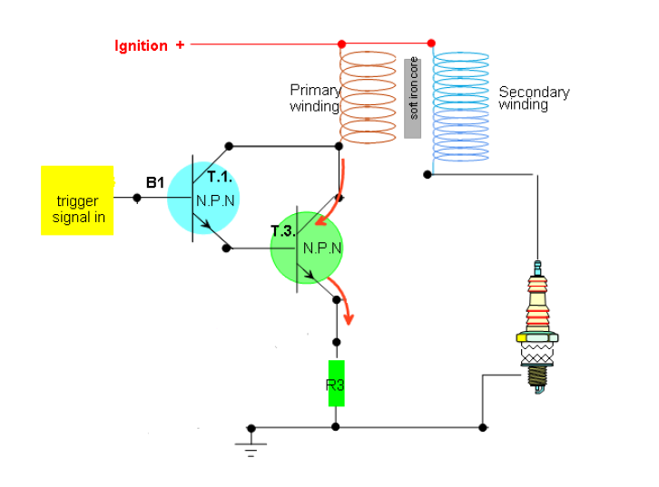
 Build the ignition circuit below on a breadboard using two 2N2222 transistors (or
equivalent)
Find the maximum current value of the transistors from the data sheet, the resistance of
the coil. Then calculate the resistor need to protect the circuit. Show calculations:
100mA maximum current from transistor.
2.1 Ohms
=12/0.1 = 120 Ohms.
The difficulty's i encountered were the circuit didn't work with the resistor in it i think this is because the diagram above has been drawn incorrectly.If i was going to build it again i wouldn't use a resistor
Subscribe to:
Posts (Atom)