Pages

Monday, September 20, 2010

TTEC 4826– Engine Electronic Control Systems Off Car


Testing a throttle position sensor (TPS)

The first TPS i tested was a potentiometer.

The TPS is used to monitor the position of the throttle in an engine.It is located on the throttle body. This effects the ignition timing and fuel injection timing.This TPS works by providing a variable resistance depending upon the position of the throttle. Resistance is in decreased in this case as more throttle is applied. It is a normally closed circuit. The voltage changes to tell the ECU or PCM when the driver is requiring more power or less power depending on throttle positioning. These sensors are adjusted by adjusting the mounting screws.


Throttle Angle Voltage

WOT = 3.9V

1/4 Throttle= 1.3V

1/2 Throttle= 2.3V

3/4 Throttle= 2.92V


Testing the throttle position switch (TPS)
PSW means power switch (WOT)
IDL means idle circuit


PSW

WOT= 0 ohms
Idle=0L

IDLE

Idle=0 Ohms
WOT= OL

The resistance changes beacuse the circuit is normally closed reading 0L and when it is switched and an open circuit it then reads 0 Ohms in both cases. the PSW circuit is only working under throttle (0 ohms) and is off (0L) during idle. The idle circuit only works at idle (0 ohms) and is off (0L) at throttle. The difference between the resistances means (0L is OFF) (0 ohms is ON). I am unsure if this throttle position sensor meets the manufacturers requirements because i dont know what kind of car this TPS was off.

Testing a MAP sensor
(Manifold Absolute Pressure)


The map sensor i tested decreased in voltage as more pressure was applied.
0 inches of mercury = 3.6V
19 inches of mercury= 1.9V
23 inches of mercury=1.4V
26 inches of mercury=1.2V
27 inches of mercury=1.2V

The map sensor is used to calculate the volume of air entering the engine and the amount. This is calculated by pressure inside the intake manifold. Most EFI systems use ethier a MAP sensor or a AFM but some use both. The map sensor then sends the signal to the ECU and the ECU delivers the correct amount of fuel. AFR (air fuel ratio). The map sensor reads pressure. when the engine is running vacuum is created inside the manifold by the movement of the pistons and the restriction created by the throttle plate. At wide open throttle vacuum drops to almost zero and pressure inside the intake manifold once again nearly equals the outside pressure. The MAP sensor is a pressure transducer which is an electrical device with a 2 chambers and a diaphragm in the middle. It detects the amount off vacuum created from the engine in one chamber and another chamber is a sealed chamber and the pressure of this chamber is calibrated to give the ECU constant measurements. This difference in pressure causes the diaphragm to bend one way or the other. The degree of deflection is measured by the strain gage and that data is relayed to the ECU.I am unsure if it meets manufactures specifications because i dont know what car it was off.

Testing a AFM (Air flow meter)
Hot wire sensor (AFM)

These sensor work by heating a wire with an electric current that is suspended in the engine’s air stream. The wire's resistance increases as the wire’s temperature increases, which limits current flowing through the circuit. When air flows past the wire, the wire cools, decreasing its resistance, which allows more current to flow through the circuit. As more current flows the wire’s temperature increases until the resistance is the same size as before ( X ohms). The amount of current required to maintain the wire’s temperature is directly proportional to the mass of air flowing past the wire. The integrated circuit converts the measurement of current into a voltage signal which is sent to the ECU.

A mass air flow sensor is used to find out the of air entering an engine. This is nessicery for the ECU to deliver the correct AFR (air fuel ratio). These sensors usually run on 5V.

The air flow meter i tested read 1V when wired up under test conditions with no air.

The voltage gradually increased as i blew through it indicating it is working correctly.

Advantages over older vane type.

responds very quickly to changes in air flow
low airflow restriction
smaller overall package
less sensitive to mounting location and orientation
no moving parts improve its durability
less expensive
separate temperature and pressure sensors are not required (to determine air volume).

Disadvantages

Hot wire can get dirty and will affects the engine operation.

Vane type Air flow meter

The vane type i tested was a BP26-13-21C


Closed throttle 4.2V
1/4 throttle 2.3V
1/2 throttle 1.9V
3/4 1.8V
WOT 1.7V

A vane, or paddle, projects into the engine’s intake air stream on a spring-loaded arm. The vane moves in proportion to the airflow, and a voltage is generated in proportion to the distance the vane moves, or the movement of the vane directly regulates the amount of fuel injected, as in the K jetronic system.

The vane moves because of the force of the air flow against it. The force depends on air density, speed and the shape of the vane.

Vane Type Disadvantages

  • it restricts airflow which limits engine potential


  • moving electrical or mechanical contacts wear out.


  • finding a suitable mounting location as it as quite large.


  • the vane has to be mounted with respect to gravity


Engine Coolant Temperature sensor


Room temperature: 2200 Ohms
30 Degrees:1800 ohms
40 Degrees:1300 Ohms
50 Degrees:1100 Ohms
60 Degrees:610 Ohms
70 Degrees:500 Ohms
80 Degrees:360 Ohms

Inside the sensor is found what is called a thermistor. This is an electronic temperature sensitive variable-resistor. The ECT is a negative temperature coefficient sensor. This means that as temperature goes up resistance and voltage goes down or vise-versa. The ECT sensor receives a 5.00 volts reference voltage from the ECU. The ECT works by changing its internal resistance according to coolant temperature and therefore also changing the voltage drop across the ECT.

Thermo fan switch


20 Degrees=0.7K ohms
30 Degrees=0.692K ohms
40 Degrees =0.580K ohms
50 Degrees=0.46K ohms
60 Degrees=0.35K ohms
70 Degrees=0.28K ohms
80 Degrees=0.22K ohms.

I am unsure if it meets manufacturers specifications because i dont know what car this thermo fan switch is off. A thermistor is a type of resistor whose resistance changes greatly with temperature. The above reading show that this is a thermistor. The resistance changes because that is how a thermistor operates. It works by turning the fan on when X amount of ohms is reached i am unsure of the exact number in this situation. This is a NTC thermistor. (Negative temperature coefficient)

Air Temperature Sensor


Room Temperature: 2480 Ohms
30 Degrees:1300 Ohms
45 Degrees:1100 Ohms
50 Degrees:1000 Ohms
75 Degrees:914 Ohms
80 Degrees:700 Ohms.

I am unsure if it meets manufactures specifications because i am unsure what car this sensor came off. It seems to be in working condition as the resistance is dropping when temperature is increased. This is a negative temperature coefficient thermistor as it decreases resistance with heat. This sensor and the engine coolant temperature sensor at 80 Degrees both were around 300 ohms. They are both temperature coefficient thermistors.
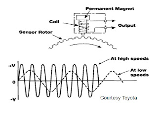
Optical Distributer


Points A,B,C.

At point B This is when the device is "on" When the chopper blade is not blocking the light.

At point A This is when the device is"off" When the chopper blade is blocking the light

At point C This is when the device is "on" again When the chopper blade is not blocking the light.


The differences between hallf effect, optical and inductive signals are inductive signals are magnetic these are signwaves and are AC voltage.This signal increases voltage and amplitude with frequency. Hall effect and optical are square waves and are ether on or off. These are more accurate than inductive because amplitude and voltage dont increase with frequency. Hall effect starts "off" and switches "on". Optical starts "on" and switchs "off".

The cams spin at half the speed of the crank. So the distributer must spin at half the speed of the crankshaft. So when the distributer turns 360 degrees the crank turns 720 degrees. If it is a 4 cylinder car the distributer will fire every 90 degrees. 6 Cylinder 60 Degrees. 8 Cylinder 45 Degrees.

Knock Sensor


Waveform is from Google images as the digital oscilloscope wasn't able to give a correct waveform because the divisions wouldn't go low enough.

The knock sensor allows the engine to run at the most advance timing possible before detonation. It advances the timing until knock is detected, A voltage is created so the timing retards. The ECU leaves the timing at right before the knocking point for optimum power and fuel economy. They create voltage because they are piezoelectric crystals.

Injector Testing.

We only had 2 injectors available to test the results were:

Injector 1
Manufacturers specifications: 14-17 Ohms
Measured at:15.5 ohms
Earth leakage test= 0L

Injector 2
Manufacturers specifications: 14-17 Ohms
Measured at: 14.0 Ohms
Earth leakage test=0L.

Heard both injectors click.

Other problems that could give the same result as an injector not firing:

Anything air, fuel or spark related will cause misfire if there is a problem within any of the systems.

Test Bench Cleaning

When removing fuel injectors the safety procautions are wear correct safety gear including overalls, eye protection. Use a fuel injector puller if you have one to avoid damaging expensive components. Dont lose the clip.

Dont know manufacturers specifications because i dont know what car they came off.
We measured a flow rate of 45ml /45cc for 60 seconds With 0 Drips.
2700ML a hour.

Out of the 4 injectors we tested 3 worked and 1 had a damaged plug so it worked intermitantly. Apart from the plug all injectors had a good spray pattern and worked well. These injectors would be fine to use again in the appropriate vechile.

Testing Ignition Coils

Coil one:
Part No. 16C6.
Voltage 6V
Primary resistance= 2.1 ohms. ( Measured)
Secondary resistance=7.5K ohms. (Measured)

Coil two:
Part No. F-088
Voltage 12V
Primary resistance 0.9 Ohms (Measured)
Secondary resistance 12.57K ohms (Measured)

Wasted Spark.

Coil primary
1= 0.7 Ohms
2=0.8 Ohms
3=0.6 Ohms

Coil secondary
1=12.2K ohms
2=12.3K ohms
3=12.3K ohms

Testing Ballast resistors
Part no: BR1
Resistance= 1.2 Ohms.


Standard Single tower coil


1. Wire up a ballast resistor in series with your coil primary winding values as shown in
the following diagram.
2. Connect an ammeter in series and note the current draw.
3. Measure and note the voltage drop across the ballast resistor.
4. Measure and note the voltage drop across the coil primary.


Current draw was 3.1A
Coil calculated voltage drop=6.51V
Coil measured voltage drop=10.6V
Ballast resistor calculated voltage drop=3.72
Ballast resistor measured voltage drop=1.3V

Wire up an ignition module using a function generator to trigger the module.
Have a coil and spark plug in the circuit so the spark plug can fire
Check with your tutor that you have done it correctly
Draw a wiring diagram of how you wired the circuit

Wire up an ignition module using a distributor to trigger the module.
Have a coil and spark plug in the circuit so the spark plug can fire
Check with your tutor that you have done it correctly
Draw a wiring diagram of how you wired the circuit


Wire up the wasted spark ignition system using the function generator to trigger the
modules.
Have the coils and sparks plug in the circuit so the spark plugs can fire.
Check with your tutor that you have done it correctly.
Draw a wiring diagram of how you wired the circuit


Wire up the coil over ignition system using the function generator to trigger the module
Have the coil and spark plug in the circuit so the spark plug can fire
Check with your tutor that you have done it correctly
Draw a wiring diagram of how you wired the circuit


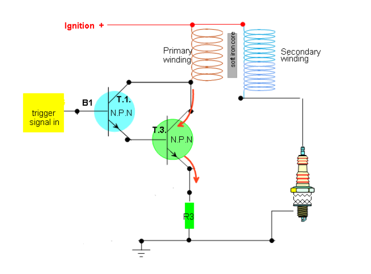
Build the ignition circuit below on a breadboard using two 2N2222 transistors (or
equivalent)
Find the maximum current value of the transistors from the data sheet, the resistance of
the coil. Then calculate the resistor need to protect the circuit. Show calculations:

100mA maximum current from transistor.
2.1 Ohms
=12/0.1 = 120 Ohms.

The difficulty's i encountered were the circuit didn't work with the resistor in it i think this is because the diagram above has been drawn incorrectly.If i was going to build it again i wouldn't use a resistor

Monday, September 13, 2010

TTEC 4825 On Car and CAN

On Vehicle testing

I identified the all of the main components for the ABS system on the vehicle we used which was a 1996 Mitsubishi galant. I identified the:

· Wheel speed sensor.
· ABS control unit
· ABS modulator
· ABS pump
· Parking brake switch
· Brake fluid level sensor
· RPM sensor
· Brake booster
· Main ABS fuse.

I know the vehicle used analogue wheel speed sensors because they only had 2 wires on the connectors.

The air gaps on all 4 wheel speed sensors were:

FR= 0.305mm, 0.12 thou (Resistance= 1.36K ohms, V= 4.7vac)
FL=0.305, 0.12 thou
RR=0.406mm, 0.16 thou
RL=0.406mm,0.16 thou.

The wheel speed sensors were in average condition. They have no problems so i wouldn't replace or do anything to them.

This is the waveform acquired from the ABS wheel speed sensor off the galant.


Using the Scan tool.

The information the scan tool showed about the ABS system is:

FRS= 16.32KM/H (Flucated a bit then stay constant , no acceleration vehicle=in drive)
FLS=16.32KM/H (Flucated a bit then stay constant , no acceleration vehicle=in drive)
RRS=0KM/H (Not rear wheel drive and car was in the air)
RLS=0KM/H (Not rear wheel drive and car was in the air)
Battery Voltage= 11.37 ( Car off) 13.6 (Car on, Alternator charging).
G sensor=0V
Stop lamp switch off.

Abbreviations

PCM= Power train control module
TCC= Torque converter clutch
TPS= Throttle position sensor
ECT= Engine coolant temperature sensor
VSS= Vehicle speed sensor
PSA= Transmission range fluid pressure switch assembly
TTS= Transmission Temperature sensor .

BLOCK DIAGRAM


WIRING DIAGRAM


SHIFT CHART


Which solenoids are on when this vehicle is shifted into drive and starts out first gear

1-2 Solenoid and 2-3 Solenoid.


Which solenoids are on when this vehicle automatically shifts into second gear.


2-3 solenoid


Which solenoids are on when this vehicle automatically shifts into third gear


Both solenoids are off.


Which solenoids are on when this vehicle automatically shifts into fourth gear.


1-2. solenoid


Fault no solenoids comes on.


Would only have 3rd gear. Would be difficult to drive really slow takes offs and wouldnt be able to do a hill start. Could go up a hill if you accelerated before.


Transmission fault code.

P0715 Honda Automatic fault code.

Means a problem with the linear solenoid. You have to flush the transmission to fix the problem.
The transmission vibrating when shifting gears. To diagnose you would have to use the scan tool and then see if you have the same fault in this case a vibrating transmission.

Fixing procedures (genuine honda)


  • Raise the vehicle on a hoist.


  • Drain the transmission. Refill it with Genuine Honda ATF.


  • Start the engine.


  • With your foot on the brake pedal, shift the transmission to D4.


  • Release the brake pedal. Press on the accelerator, and bring the speedometer up to 50 mph. Make sure the transmission shifts through the first three lower gears and into fourth, and that the torque converter locks up.
    Apply the brakes to stop the front wheels.


  • Shift to reverse, and then to neutral.


  • Repeat the shifting procedure (steps 4 through 7) four more times.


  • Turn off the engine.


  • Repeat the above drain, refill, and shifting procedure (steps 2 through 9) two more times.


  • Drain the transmission. Reinstall the drain bolt with a new washer. Refill the transmission with Genuine Honda ATF.


P0752 Shift Solenoid A Stuck On. (Mercedes benz)


To diagnose this problem you would have to have a shift chart for mercedes benzdriving the vehcile with a scan tool and seeing which solenoids are open and closed.. This would mean the car would have 1 or 2 gears or possibly no gears. You could tell by


To fix the problem you would have to take gearbox apart and rebuild it.


Solenoid positions (1996 Mitsubishi Galant)


Used the Hanatech multiscan P1 scan tool to identify the solenoid positions.


The Solenoids are: 2ND, OD, LR, UD


A torque converter is a type of fluid coupling, which allows the engine to spin independently of the transmission. If the engine is turning slowly, such as when the car is idling at traffic lights, the amount of torque passed through the torque converter is very small, so keeping the car still requires only a light pressure on the brake pedal.


The torque converter comes on during gear changes. Used to separate the engine from the gearbox similar job to a mechanical clutch. The brake pedal engages the torque converter.


CAN WORKSHEET.


The wires are twisted every 20-30mm to prevent capacitance , reduces EMF noise and radio interference. Resistance, Capacitance, length and resistance must remain the same or the signal will be different.


CAN (TYPE C) Capable of high speeds (256KBS-1MBS) is used for important ECUS such as the ABS ECU, Powertrain controls and Emission controls. Not fault tolerant. Should be 60 ohm. (two 120 ohm resistors in parallel).


CAN (TYPE B) is the slower more fault tolerant type is used for less important electrics such as door locks and comfort devices such as heaters/aircon. As long as one wire of the two wires has potential voltage difference from ground, bus should be able to operate.
CAN B may operate in “1 wire mode” with voltage @ 1.2 v.


I used a 2003 land rover.


I used the twisted pairs from the ABS modulator.


Aliasing is an effect where the original signal can become unreadable. Also a distorted or noisy signal. The below waveforms are not aliasing because they are read-able and we used the correct time division.


The voltage on the main line of (1.3) was 2.63V. When it was talking voltage became 2.3V. This is the high speed line.


The voltage on the main line of(1.4) was 0.25V. When it was talking the voltage became 0.18V. This is the low speed line.


This is the waveform from the wires yellow & brown (1.3)


The time divison is 20ms and voltage was 1v per divsion.

Waveform from wires yellow and black


Scan tool observations

The Vehcile i used was the land rover 2003.
I used the scan tool Autoboss (star) for the observations

The different system that are controlled by CAN in this vehicle are:


EHC/EHC2 Electrical ride height level (FAST)


ABS/STABILITY Control (FAST)


EDC Electronic Damper control (FAST)


SRS Airbag (SLOW)


ZKE Body electronics (SLOW)


IHKR Heater/Aircon (SLOW)


IKE Instrument cluster (SLOW)


Steering angle sensor (FAST)


DME/DDE motor & Petrol electronics (FAST)


EMC electronic engine power control (FAST)


EGS Electronic Transmission Control. (FAST)


EWS Vehicle immobilizer (SLOW)


CR Cruize control. (SLOW)


THE DIFFERENT FUNCTIONS OF THE SCAN TOOL ARE:


Print screen.


Portrait / Landscape


Demo


Quickscan


manual scan


Diagnostic.

Wednesday, September 8, 2010

TTEC 4825 Waveforms


This is an analogue waveform with a frequency of 0.5HZ and a maximuim of +3V.


Wheel Speed sensor waveforms.


The waveforms were similiar on all wheels the only difference being that both the left wheels were 1V and the right wheels were 1.5V.
The AC voltage across each wheel speed sensor was:
Left Front 3.5V (AC) Resistance=1.4K ohms
Left Rear 2.5V (AC) Resistance=1.43K ohms
Right Rear 5.2V (AC) Resistance=1.6K ohms
Right Front 4.4V (AC) Resistance=1.62K ohms.
Advantages of an oscilliscope over a multimeter.
An oscilliscop can identify a noisy signal or a problem like a chipped tooth rotor because there will be a huge drop off point in the signal which a voltmeter couldnt identify. The oscilliscope is a more accurate tool for diagnosing ABS wheel speed sensor. if the signal was noisy the sensor could be faulty or maybe have iron shards stuck to the magnet. This couldnt be identified by the multimeter.


Show a digital signal switching 5V every 2 seconds


ABS relay waveform (1) Power something in the ABS system.


This is showing the relay switching the ABS motor on. Changing from the control to the switching circuit inside the relay.

ABS waveform switching the ABS pump on.


This is showing the relay switcing the pump on. The voltage change between the control and switching circuit.

Fault Check:

When the key is turned to ignition the ABS system does a fault check. If any faults are detected the ABS warning lamp will stay on constantly and ABS won't work. The ABS warning lamp should stay on for 6 seconds during the self test and then turn off. In some cars it will only turn off after 8km/h. During the self test the ABS pump turns off and on. There was power at the motor wires for one second at the relay to turn the motor on.


Create a fault and observing.

I created a fault in the ABS system by slowing down the front left wheel speed sensor. The ABS warning lamp was constantly on. The ABS pump turned on as soon as the wheel speed sensor was slowed down this is because the ABS would think that wheel is locking/ skidding so it released the pressure at that wheel. The pressure gauge read almost 0psi on the front left wheel when slowed.This is how ABS functions.

ABS solenoid actuated waveform


Used pin 1.


This is showing the solenoid switching on and then off to release brake presssure

Wednesday, September 1, 2010

TTEC4825 - Vehicle Safety, Transmission and Can systems

Possible damages for ECUs include
  1. Spiked by careless arc welding.
  2. Enclosure seal damaged and obvious signs of water ingress

  3. Obvious signs of physical damage to the ECU enclosure.

Faults are equally likely to be connections or sensors depending on the condition of the car, how it has been driven or the previous technician that have worked on the vehcile. For an inexperienced technicion to diagnose an ECU.Check for the easyist faults first. The first check should be checking for a damaged enclosure seal or signs of water or physical damage to the ECU casing. If there is no damage then proceed to check the wheel speed sensors, the pump, the hydraulic regulator, brake booster, master cylinder and all connections and brake lines. If no problems are found in other components of the ABS system it is most likely the ECU has been shorted or damaged. Next step would be to try another ECU to see if the problem has been fixed.

What is ABS?

ABS stands for anti-lock braking system. It stops the wheels from locking or ceasing to rotate under heavy braking. When the wheel is rotating the driver can maintain steering control. It works by altering the pressure between wheels. It gets signals from wheel speed sensors detecting what speed and if the wheel is skidding. If any fault occurs in the system an ABS light will emit constantly on the dash and you will stil have normal braking. When skidding is detected the ABS ECU actuates the valves to reduce hydraulic pressure to the brake at the affected wheel, thus reducing the braking pressure on the wheel. This process is repeated continuously. A typical anti-lock system can apply and release braking pressure up to 20 times a second

Different ABS configurations:

­Four-channel, four-sensor ABS
This is the best scheme. There is a speed sensor on all four wheels and a separate valve for all four wheels. With this setup, the controller monitors each wheel individually to make sure it is achieving maximum braking force.
Three-channel, three-sensor ABS
This scheme, commonly found on pickup trucks with four-wheel ABS, has a speed sensor and a valve for each of the front wheels, with one valve and one sensor for both rear wheels. The speed sensor for the rear wheels is located in the rear axle.
This sys­tem provides individual control of the front wheels, so they can both achieve maximum braking force. The rear wheels, however, are monitored together; they both have to start to lock up before the ABS will activate on the rear. With this system, it is possible that one of the rear wheels will lock during a stop, reducing brake effectiveness.
One-channel, one-sensor ABS
This system is commonly found on pickup trucks with rear-wheel ABS. It has one valve, which controls both rear wheels, and one speed sensor, located in the rear axle.
This system operates the same as the rear end of a three-channel system. The rear wheels are monitored together and they both have to start to lock up before the ABS kicks in. In this system it is also possible that one of the rear wheels will lock, reducing brake effectiveness.
This system is easy to identify. Usually there will be one brake line going through a T-fitting to both rear wheels. You can locate the speed sensor by looking for an electrical connection near the differential on the rear-axle housing.

http://en.wikipedia.org/wiki/Anti-lock_braking_system

Wiring Diagram Practise


Parts of an ABS system

1: Rotor

2: Wheel speed sensor

3. Toothed rotors

4. Hydraulic modulator.

5. Master Cylinder

6. Caliper

7. Brake booster.

More Parts

1. ABS Inspection Connector Box

2. Right-rear Wheel Sensor

3. Left-rear Wheel Sensor Connector

4. Left-rear Wheel Sensor


5. Right-rear Wheel Sensor Connector

6. Under-dash Fuse/Relay Box

7. Left-front Wheel Sensor

8. Under-hood Fuse/Relay

9. Left-front Wheel Sensor Connector

10. Under-hood Relay Box

11. Right-front Wheel Sensor

12. Right-front Wheel Sensor Connector.

13. Modulator Unit

14. ABS Control Unit


15. Service Check Connector

Practise Diagrams


Wheel Speed Wire colour:


Front right: W&B

Front left: R&B


Rear left: L&P


Rear right: Br&Y

ABS wheel speed sensors use braided wire because they act as a grounding strap preventing static build up and for shielding purposes as they are located in a rough enviroment.


The fuses are the ABS circuits above are 50A ( Main fuse ) 10A (Gauge Fuse) 20A (Done Fuse) 15A ( stop fuse) 15A (ECU-1G)


Identify which solenoid controls which wheel speed sensor. Then note pins and colour

Front Right wheel: Pin number 6. Colour: R-W, R-G.

Front Left wheel: Pin number 2. Colour: L-R, L-W

Rear Left wheel: Pin number 1,5. Colour Br-w, Br-r

Rear right wheel: Pin number 4,8. Colour G-B, G-Y

ABS Solenoid positions under different braking conditions

Under normal braking conditions the inlet valve will be open and the outlet closed.

When the ABS is working to reduce pressure the inlet valve will be closed and the outlet valve open.

When the ABS is working to hold pressure both the valves are closed.

When the ABS is working to increase pressure the inlets open and outlet closed.


The ABS motor will be working on all the above conditions exept for normal braking.


ABS Demonstrators


The ECU pin outs for the wheel speed sensors are

Left front: ECU pin number 4 and 5 (B19)

Left rear: ECU pin number 7 and 9 (B21)

Right front ECU pin number 11 and 21 (B20)

Right rear ECU pin number 24 and 26 (B22)


They are Inductive, also called Magnetic analogue speed sensors they create a digital waveform. I know they are analogue beacuse they have 2 wires.

How they work


A toothed rotor containing iron teeth, rotates in relation to the speed of the wheel. A magnetic pickup has a magnet which changes reluctance as the magnet is near or far from the iron teeth of the rotor. Iron makes the magnet feel stronger or weaker depending on the distance. The moving field flux lines generate an AC voltage which is induced in to the wires around the magnet. The AC voltage signal is then sent to the ECU. The ECU will know how fast each wheel is rotating. These are passive because they can work without voltage from the ECU. They create digital waveforms. Low speed produces low voltage and a slow frequency and high speed produces a high speed voltage and high frequency.


ABS Relays

From the above circuit diagrams i located the relays that power the ECU, the pump and the solenoids.

ECU relay= K38

Pump relay=K100

Solenoid relay= K39

ECU pin 1 brings power to the ABS ECU.

ECU pin 27 controls ABS ECU relay.

ECU pin 30 brings power to ABS pump.

ECU pin 28 brings power to ABS pump relay.