Injector fuel circuit Diagram.
Reference voltage at TPS sensor
The voltage was 4.98V on the reference wire. The purpose off this voltage is to power the TPS. If the voltage was larger then 5V then you would probably get high idle. If it was lower than 5V then you would have a low idle. The ECU wont know when the throttle is being pressed in ether condition. So you would have low power. If there wasnt 5V at the TPS this could be from incorrectly wired or a dirty wire / bad connection or even a faulty ECU
Ground TPS Sensor.
The voltage i recorded was 0.053V.
This voltage shows this is a good ground as there is little resistance. If the ground is not good it could be from dirty wires, damaged connectors or faulty ECU.
Throttle position sensor return/output.
With the ignition on the reading on the TPS signal wire was 0.543V.
Throttle at around half throttle 1.983V.
Throttle at WOT=4.1V
When slowly opening the throttle there were no sudden jumps or gaps when the voltage was increasing. The b16a did not have 4 wires.
How the TPS works.
The TPS is used to monitor the position of the throttle in an engine.It is located on the throttle body. This effects the ignition timing and fuel injection timing.This TPS works by
providing a variable resistance depending upon the position of the throttle. It is a normally closed circuit. The voltage changes to tell the ECU or PCM when the driver is requiring more power or less power depending on throttle positioning. These sensors are adjusted by adjusting the mounting screws. the TPS is a potentiometer a varaible resistor depending on the throttle angle.
When the throttle is closed the TPS should read 0.5-0.7V depending on specifications at WOT the voltage should be 4-5V depending on the specific vehicle. At WOT fuel trim and ignition timing is changed.
If the voltage wasn't correct at the ECU the problems could be
dirty wires, damaged connectors , damaged TPS or faulty ECU.

Throttle Position Switch
Idle Wire Color Teal
Volts at Idle=9V.
Volts at WOT=12mV.
WOT wire Color Green
Volts at idle 10mV.
Volts at WOT=9V
This output is needed so the ECU knows the position of the throttle. This is important to control The ignition timing and fuel injection timing. The fuel injector duration will increase at WOT.
Engine coolant temperature sensors
The ECT supply wire red 3V when engine was cold with ignition on. This voltage seems correct for a cold engine.
When the engine was warmed up for 2 min the ECT voltage was now 2.6V.
Yes this showed a lower voltage as the engine increased in temperature.
How the ECT works
Inside the ECT sensor is found what is called a thermistor. This is an electronic temperature sensitive variable-resistor. The ECT is a negative temperature coefficient sensor. This means that as temperature goes up resistance and voltage goes down or vise-versa. The ECT sensor receives a 5.00 volts reference voltage from the ECU. The ECT works by changing its internal resistance according to coolant temperature and therefore also changing the voltage on the signal/output.
When the Engine is cold more fuel is required and this is determined by the ECT voltage at the ECU. If the ECT had a fault or was disconnected the ECU would have constant 5V and the engine would constantly run rich or if the voltage was stuck low the engine would struggle to idle when cold.
If the voltage wasn't correct at the ECU the problem could be
dirty wires, damaged connectors , damaged ECT or faulty ECU.
Ground ECT.
The ground on the ECT was 7mV.
This voltage shows this is a good ground because there is very little resistance in the wire/connection.

RPM sensor CKP
With the engine idling there was 6.20VAC.
Engine RPM at 2500=9.6VAC
DC volts at Idle=2.5mV.
Engine RPM at 2500 (DC VOLTS)= 3.5mV.
Hertz= 550hZ at idle.
The best test setting was AC volts
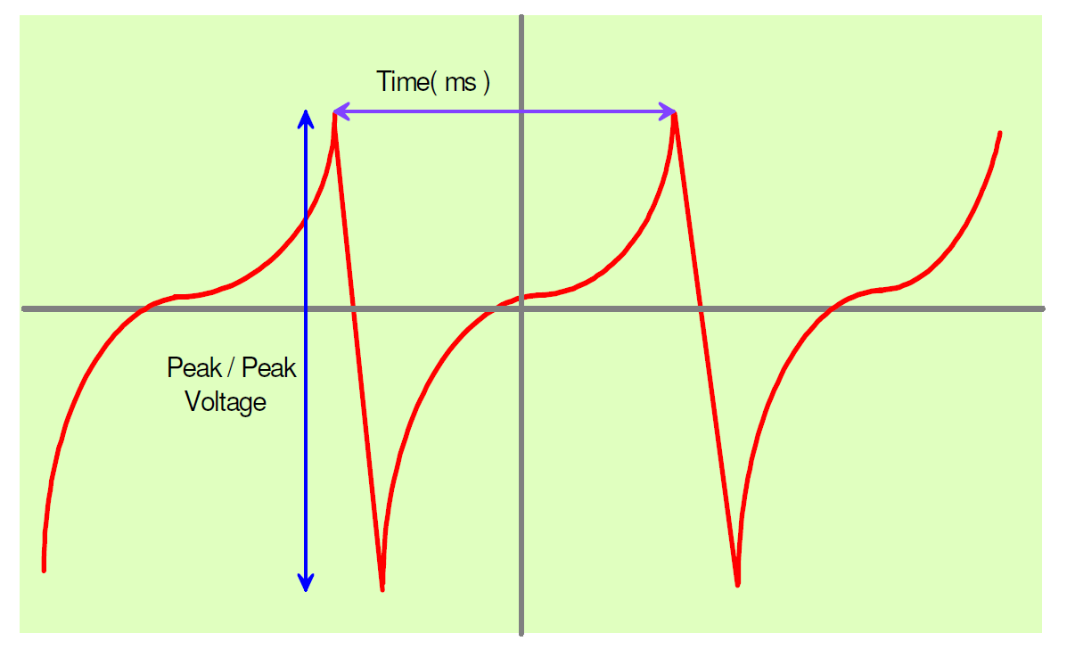
This RPM/ CKP sensor is inductive or magnetic.
This type of sensor is an AC (alternating current) generator.
When it is rotating it generates an AC voltage which increases in frequency and amplitude
with an increase in the speed of rotation. This works with a magnet and a pick up coil. As the air gap/ distance from the magnet gets further away voltage gets lower and when it gets closer voltage gets higher. The waveform looks like this.

The most accurate function to use to check this sensor output is AC voltage on a multimeter. If the voltage increases steadily with engine RPM then the sensor is atleast partially working.. This is not as accurate as using an oscilloscope.
If the ECU did not receive the correct voltage this could be from a bad connection / dirty connection. A broken sensor or even a faulty ECU. If the ECU doesn't receive a signal the engine will cut out and injection will stop.
MAP SENSOR
With the ignition on the MAP sensor read:2.88V
With the Engine idling the MAP sensor read:0.88V
With a short sharp acceleration the MAP sensor read 1.98V
How the MAP sensor works:
The map sensor is used to calculate the volume of air entering the engine and the amount. This is calculated by pressure inside the intake manifold. Most EFI systems use ethier a MAP sensor or a AFM but some use both. The map sensor then sends the signal to the ECU and the ECU delivers the correct amount of fuel. AFR (air fuel ratio). The map sensor reads pressure. when the engine is running vacuum is created inside the manifold by the movement of the pistons and the restriction created by the throttle plate. At wide open throttle vacuum drops to almost zero and pressure inside the intake manifold once again nearly equals the outside pressure. The MAP sensor is a pressure transducer which is an electrical device with a 2 chambers and a diaphragm in the middle. It detects the amount off vacuum created from the engine in one chamber and another chamber is a sealed chamber and the pressure of this chamber is calibrated to give the ECU constant measurements. This difference in pressure causes the diaphragm to bend one way or the other. The degree of deflection is measured by the strain gage and that data is relayed to the ECU. This has a voltage on the output wire which goes to the ECU that tells it how much air is entering the engine.
The above readings are correct for the engine as the engine runs good with no problems.
If the ECU did not receive the correct signal this could be from faulty wiring, bad connections , faulty ECU, Faulty MAP or a vacuum leak
Diagram MAP.
MAF sensor:
With ignition on voltage was 3.1V.
With engine at idle voltage was 1.3V.
Short sharp acceleration was 2.1V.
How MAF works.
These sensor work by heating a wire with an electric current that is suspended in the engine’s air stream. The wire's resistance increases as the wire’s temperature increases, which limits current flowing through the circuit. When air flows past the wire, the wire cools, decreasing its resistance, which allows more current to flow through the circuit. As more current flows the wire’s temperature increases until the resistance is the same size as before ( X ohms). The amount of current required to maintain the wire’s temperature is directly proportional to the mass of air flowing past the wire. The integrated circuit converts the measurement of current into a voltage signal which is sent to the ECU.
The MAF readings are correct because the engine runs good with no problems.
If the ECU did not receive the correct signal this could be from faulty wiring, bad connections , faulty ECU, Faulty MAF.
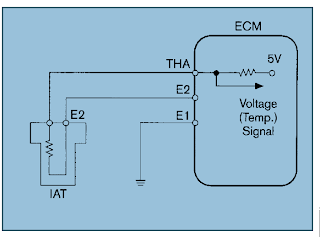
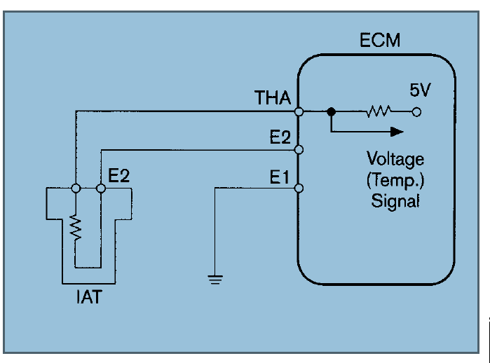
Intake Air temperature sensor
Ignition on voltage was:1.93V
Less Than ECT.
This shows the IAT sensor is hotter than the ECT. Which means the engine is cold.
How it works
The Intake Air Temperature (IAT) sensor resistance changes in response to the intake air temperature. The sensor resistance decreases as the surrounding air temperature increases. This provides a signal to the PCM, indicating the temperature of the incoming air charge.
The IAT effects the ECU outputs for fuel injection because it compares this temperature (voltage) to the ECT to know if it is a cold start. ECT cold and IAT hotter for a cold start.
The following symptoms can be caused by a faulty IAT sensor due to loose connections, bad grounds, high resistance in the circuit, or opens in the circuit. Faulty ECU.
The IAT sensor should decrease in voltage with temperature.