- Spiked by careless arc welding.
- Enclosure seal damaged and obvious signs of water ingress

- Obvious signs of physical damage to the ECU enclosure.

Faults are equally likely to be connections or sensors depending on the condition of the car, how it has been driven or the previous technician that have worked on the vehcile. For an inexperienced technicion to diagnose an ECU.Check for the easyist faults first. The first check should be checking for a damaged enclosure seal or signs of water or physical damage to the ECU casing. If there is no damage then proceed to check the wheel speed sensors, the pump, the hydraulic regulator, brake booster, master cylinder and all connections and brake lines. If no problems are found in other components of the ABS system it is most likely the ECU has been shorted or damaged. Next step would be to try another ECU to see if the problem has been fixed.
What is ABS?
ABS stands for anti-lock braking system. It stops the wheels from locking or ceasing to rotate under heavy braking. When the wheel is rotating the driver can maintain steering control. It works by altering the pressure between wheels. It gets signals from wheel speed sensors detecting what speed and if the wheel is skidding. If any fault occurs in the system an ABS light will emit constantly on the dash and you will stil have normal braking. When skidding is detected the ABS ECU actuates the valves to reduce hydraulic pressure to the brake at the affected wheel, thus reducing the braking pressure on the wheel. This process is repeated continuously. A typical anti-lock system can apply and release braking pressure up to 20 times a second
Different ABS configurations:
Four-channel, four-sensor ABS
This is the best scheme. There is a speed sensor on all four wheels and a separate valve for all four wheels. With this setup, the controller monitors each wheel individually to make sure it is achieving maximum braking force.
Three-channel, three-sensor ABS
This scheme, commonly found on pickup trucks with four-wheel ABS, has a speed sensor and a valve for each of the front wheels, with one valve and one sensor for both rear wheels. The speed sensor for the rear wheels is located in the rear axle.
This system provides individual control of the front wheels, so they can both achieve maximum braking force. The rear wheels, however, are monitored together; they both have to start to lock up before the ABS will activate on the rear. With this system, it is possible that one of the rear wheels will lock during a stop, reducing brake effectiveness.
One-channel, one-sensor ABS
This system is commonly found on pickup trucks with rear-wheel ABS. It has one valve, which controls both rear wheels, and one speed sensor, located in the rear axle.
This system operates the same as the rear end of a three-channel system. The rear wheels are monitored together and they both have to start to lock up before the ABS kicks in. In this system it is also possible that one of the rear wheels will lock, reducing brake effectiveness.
This system is easy to identify. Usually there will be one brake line going through a T-fitting to both rear wheels. You can locate the speed sensor by looking for an electrical connection near the differential on the rear-axle housing.
http://en.wikipedia.org/wiki/Anti-lock_braking_system
Wiring Diagram Practise
Parts of an ABS system
1: Rotor
2: Wheel speed sensor
3. Toothed rotors
4. Hydraulic modulator.
5. Master Cylinder
6. Caliper
7. Brake booster.
More Parts
1. ABS Inspection Connector Box
2. Right-rear Wheel Sensor
3. Left-rear Wheel Sensor Connector
4. Left-rear Wheel Sensor 
5. Right-rear Wheel Sensor Connector
6. Under-dash Fuse/Relay Box
7. Left-front Wheel Sensor
8. Under-hood Fuse/Relay
9. Left-front Wheel Sensor Connector
10. Under-hood Relay Box
11. Right-front Wheel Sensor
12. Right-front Wheel Sensor Connector.
13. Modulator Unit
14. ABS Control Unit
15. Service Check Connector
Practise Diagrams

Wheel Speed Wire colour:
Front right: W&B
Front left: R&B
Rear left: L&P
Rear right: Br&Y
ABS wheel speed sensors use braided wire because they act as a grounding strap preventing static build up and for shielding purposes as they are located in a rough enviroment.
The fuses are the ABS circuits above are 50A ( Main fuse ) 10A (Gauge Fuse) 20A (Done Fuse) 15A ( stop fuse) 15A (ECU-1G)
Identify which solenoid controls which wheel speed sensor. Then note pins and colour
Front Right wheel: Pin number 6. Colour: R-W, R-G.
Front Left wheel: Pin number 2. Colour: L-R, L-W
Rear Left wheel: Pin number 1,5. Colour Br-w, Br-r
Rear right wheel: Pin number 4,8. Colour G-B, G-Y
ABS Solenoid positions under different braking conditions
Under normal braking conditions the inlet valve will be open and the outlet closed.
When the ABS is working to reduce pressure the inlet valve will be closed and the outlet valve open.
When the ABS is working to hold pressure both the valves are closed.
When the ABS is working to increase pressure the inlets open and outlet closed.
The ABS motor will be working on all the above conditions exept for normal braking.
ABS Demonst rators
The ECU pin outs for the wheel speed sensors are
Left front: ECU pin number 4 and 5 (B19)
Left rear: ECU pin number 7 and 9 (B21)
Right front ECU pin number 11 and 21 (B20)
Right rear ECU pin number 24 and 26 (B22)
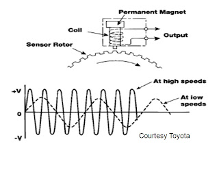
They are Inductive, also called Magnetic analogue speed sensors they create a digital waveform. I know they are analogue beacuse they have 2 wires.
 How they work
A toothed rotor containing iron teeth, rotates in relation to the speed of the wheel. A magnetic pickup has a magnet which changes reluctance as the magnet is near or far from the iron teeth of the rotor. Iron makes the magnet feel stronger or weaker depending on the distance. The moving field flux lines generate an AC voltage which is induced in to the wires around the magnet. The AC voltage signal is then sent to the ECU. The ECU will know how fast each wheel is rotating. These are passive because they can work without voltage from the ECU. They create digital waveforms. Low speed produces low voltage and a slow frequency and high speed produces a high speed voltage and high frequency.
ABS Relays
From the above circuit diagrams i located the relays that power the ECU, the pump and the solenoids.
ECU relay= K38
Pump relay=K100
Solenoid relay= K39
ECU pin 1 brings power to the ABS ECU.
ECU pin 27 controls ABS ECU relay.
ECU pin 30 brings power to ABS pump.
ECU pin 28 brings power to ABS pump relay.
Hey Friends, if you are searching the best supplier of laboratory equipment on best price, then you should check out www.aticoexport.com. It is a brand that is very famous as the manufacturer and supplier of scientific equipment.
ReplyDelete